
My version of wax injector
Main problem we face during development of wax injector with large wax chamber inside is how to distribute even temperature over the whole volume. The aim is to keep wax neither in hard nor in liquid condition, but in paste condition. Because the main process within wax occurs namely during transition from liquid to paste-shaped condition. For example, melting point of wax Castaldo red is + 74 °Celsius, for Castaldo yellow is +76° Celsius. The situation is additionally complicated due to the fact that wax has very high warm conductivity. Therefore the warm inertia is high. You know very well time period you should switch on the heat mode on beforehand, in order to obtain the evenly temperature distribution on the whole volume.
The solution to divide the inner volume by reinforcing ribs, connected to
warming devices. But there is a problem to have a service of this pot (cleaning,
wax change etc.). Here I tried to solve this problem, without taking into
account the spent time and used materials.
Certainly, this approach is not ideal. Because the pot and nozzle could be
made from silver (due to its maximal warm conductivity). But I recognize the
barriers of my fantasy. (And to drill the pot from solid piece of silver with
diameter of 230 mm it would be too expensive :).
So, heart of device is pot vessel for wax. Which material should be
selected?
Hereby please the chart of warm conductivity W/mhk (there are estimated
values due to differences in several referring documents):
- Silver: 430
- Cooper: 413
- Aluminium: 237
- Bronze: 100
- Brass: 100
- Iron: 100
- Tin: 73
- Inox steel: 45
- Lead: 37
So, silver as material is really too expensive.
Cooper is difficult to be turned, it can be winded and soldered.
Bronze, brass as we see, the ccoper-based alloys have worser warm
conductivity, but these metals are easier to be turned.
Pewter, solder alloy warm conductivity is low.
Carbon steel the same problem; inox steel is even worser (although the
material seems to have any advantages).
So, let`s make choice on aluminium.
After search in garage, I found suitable part - previous cap dismantled from
some device. Wall thickness is 10 mm, material aluminium, with mounting ear
holes. Volume is about 3L. I had to make another turning on the flange. Then it
made me glad: to have this part means 90% of general success. The rest will be
configurated around this main part.
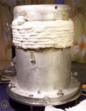
But on the picture you can see muffle oven assembled: heating element and
connected flange.
Having container for wax, let`s search for device`s body. In first I planned
to build the housing from buffed inox steel. I thought: It has low warm
conductivity and therewith - buffed surface can reflect the warm emission. But
the perspective to see everyday the distorted reflected picture of myself didn`t
arise caused any excited feelings in me. That`s why I decided to make housing
from common carbon steel of suitable diameter. After that it is needed to be
painted properly. I used car-paint in sprayer. Diameter is determined by
diameter of suitable pipes available (I hope you will not plan to turn housing
from solid piece of metal). In my case it was piece of pipe D=200 mm, modified
by turning.
Turning shold be made not too much, just suitable for putting insulating
inside.
Picture of right now painted housing:
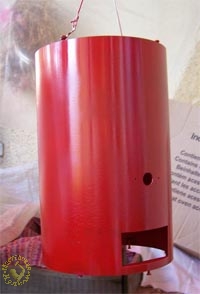
On the face side there is nozzle, excavation for controller (will be more
explained), on the back side ther are holes for fuse, switcher and perforation
for warm exhaust from controller.
Now it`s the correct time to show you the drawing. Pleased have a look:
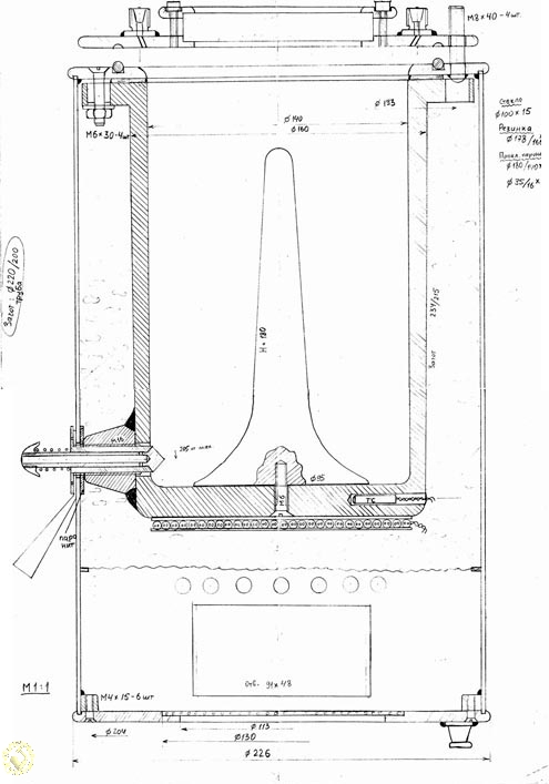
But after having some thoughts I decided to make the device with changes, not
strictly in accordance with drawing.
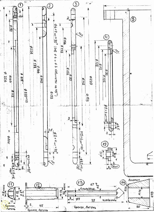
Explanations are needed. Mounting drawing is not a final control drawing in
my understanding. Because I made the rough drawing and put fastenings, control
window etc. in one plane (due to place saving). But you can see on picture and
explanation note how the device look like.
To warm up the wax in tank with inner diameter of 140 mm is hardly difficult.
You will need a lot of time. And - therewith heat capacity of wax is rather
high. That`s why the warm compresses we make based on wax. Wax has a long warm
up time as well as a cool down time.
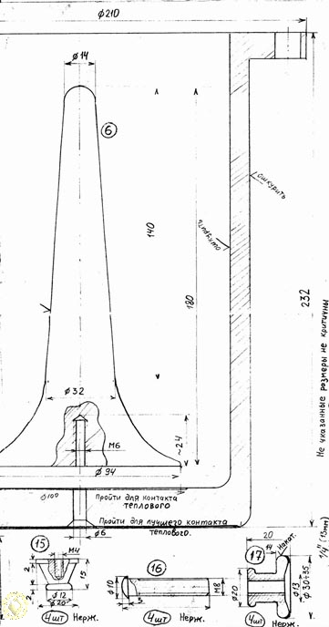
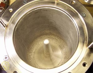
Having analyzed the construction with inner ribs, partitions etc., and taking
into account that for cleaning it is needed to touch with hand the bottom, O
decided to use the cone from the same aluminium.
Within its moving down, wax will get in narrow place and will be heated more
(exactly what I need). And - therewith cooling of cone is better due to its
large base square. Cone`s base I fixed with silicon-organic glue. It is called Vixint, of type U-1-18. It is composite of 2 components. After polymerization
you receive silicon rubber. It is rather elastic. It thermo-resistant until +350
deg Celsius. I checked it by myself. Instead of Vixint, you can use car-sealant,
it is effective until +300 deg Celsius.
I added the catalyzer acc.to schedule: 0,4% - 24 hrs before polymerization,
up to 3% - 20 minutes. Than I fixed it by screw M6 to the bottom.
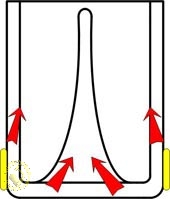
By horizontal positioning of the heater, the heat will be distributed acc. to
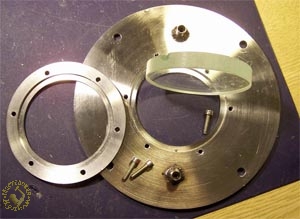
following scheme. The tank is hanged on upper ring due to the flange. There is
rubberized asbestos fabric gasket sealed by Vixint is positioned between tank
and ring. Gasket is as an additional insulate item.
The upper ring is with groove made for rubberized ring. The corresponding
groove is made on cover.
One more option. In order to check how much wax is remained in tank, there
should be made a looking window. It avoids us from confused situation. Let`s
imagine: Tank is without looking window. You increase heat input, more and more,
and after opening you recognize there is nothing in, air only. So you need to
feed with wax, warm again etc. It causes time spending.
I glued window to the cover due to Vixint. Please don`t forget to put Vixint
on screw thread before mounting!
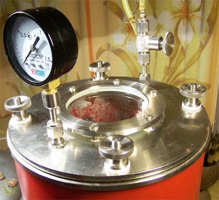
I`ve chosen the glass with thickness of 15 mm. it is enough to ensure the
personal safety during work. There are 2 fittings for air feeding from pump
and for manometer.
There is everything clear with manometer. You can select anyone with measurement scale 0 up to 1,6 or 2 kg/cm2. But the valve (see on the picture) is special one. The pipe is open in this area everytime. And if you turn the valve clock-counterwise, the air will go out from the pipe through the hole in body.
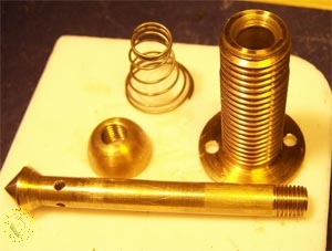
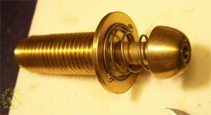
So, now about injection. I decided not to make the case more complicated than it is. Traditional construction (see on the picture) if assembled properly will have its positive impact. Cooling if we have pipe long enough will be sufficient. Material is brass. Parts made from brass are more match-able. Because we have to achieve the sliding if we have long enough bar. Let`s increase the air permeability by using a cone. The cones in shooting m (on the pipe and in spare bag) are turned as well? But for sure - you are to wash enough with special compound. We will spend about one hour, but it is worth of it. In order not to spoil the mood, because of blowing effect (by device :).
So, electrical circuit plan. Controller is OVEN TPM1-TSCH2.TC.R
Legend:
TSCH2 type of housing. Other types are more bulky
TC thermoresistance. Compared with thermocouple, thermoresistance on small
temperatures is more exact.
P type of outcome relais. Contacts up to 8A. This is totally enough
Control principle: two positioned.
You can buy the box of another type and accessories: with thermocouple, with
connection to tiristor etc. Instead of those idea you can use PID controller,
stepwise warming up etc. but all those items are not suitable. As the reality
shows, oscillations of temperature on the area heater-thermoresistance are not
more than some degrees around of equipment. But in the mass if wax, the
oscillations will be flatten at all.
I made the connection as shown below
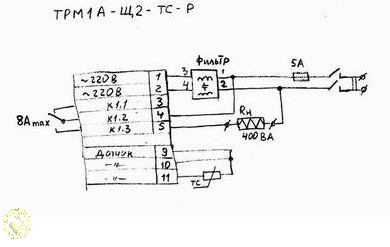
On the plan everything what is positioned right of the terminals of
controller these are extern devices.
TS thermo-resistance of type cooper, nominal 50 Ohm (TCM-50M). Rn-load
(heater itself). Than fuse and switcher. I protected the controller by using
the surge protector. This device will protect the controller during voltage
jumps after power switch on. Application of surge protector is not necessary,
but it`s better to use it. I made connections as follows:
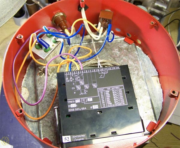
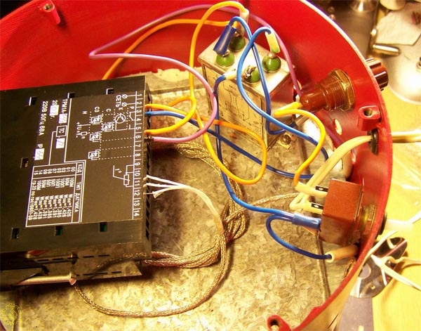
Square tin plate with reinforcement ribs gives support of
thermo-insulation. There are 4 earings welded to inside of housing. You should
drop the plate and turn, while positioning of edges behind of the earings. I
fixed the filter.
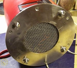
Please pay attention to perforation area of housing and bottom. The
controller needs to be cooled.
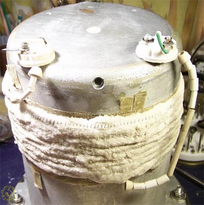
Now about heater. I selected the power of heater based on experience. The
reason is: Inintially I found out the official information of the ready-plant
built models. It resulted in a very large variety from 50 up to 350(!) W per
liter of wax. During my tests I`ve selected 268WA for volume 3 L
So:
Nichrome diameter 0.4
Current 1,22A
Resistance of heater 180 Ohm
Having resistance for this diameter 8.52 Ohm/m I calculated length of wire
21m. Certainly it is not convenient to operate this length. You should wind up
the wire on the appropriate core bar. There is a hole for temperature sensor
shown on the picture.
After positioning of sensor, the free space should be filled by talc and be
tamped. Generally, you should make the warm connection of sensor with heater as
maximal as possible, due to reduction of hysteresis losses.
A few words about mixture
I decided to search for new compounds due to the scope of reasons: liquid
glass has not solidification level enough, I had no rests of kaolin, sealant for
fireplace is too expensive, fireclay is not well enough. So I developed my
compound:
- Mortar sand 2 parts
-Corundum milled 1 part
Than I added orthophosphoric acide (70%).
You shall put fiberglass with mica on the housing. Than you should put the
winded nichrome, controlling the gaps between the coils and - after that- to put
sealant all unsealed places by as following: it makes no sense to wait until it
will be hard. So you have to warm it up. It`s very easy. You should connect it
to power system. It will be a little bit swollen. It`s quite all right. It`s
solid piece
On the ends of nichrome I fixed ceramics, these ends I fixed by using of
ceramic glasses from old glow lamps. Than I connected it with power cable. It
means, please don`t utilize old ceramic parts (from electric irons, electric
cooking plates etc.).
As for insulation. You can use various materials: beginning from tow,
silicate cotton, up to mullite mattress. Having troubles (skin irritation) after
work with silicate cotton, I`ve chosen old terry-towels and felt. Because the
working temperature is not high. Even while working with hand-made types of wax
I had the working temperature below +100°Celsius.
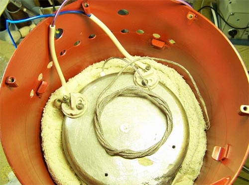
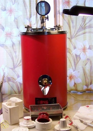
So, let`s assembly all the parts. Here you can see the result (already in operation):
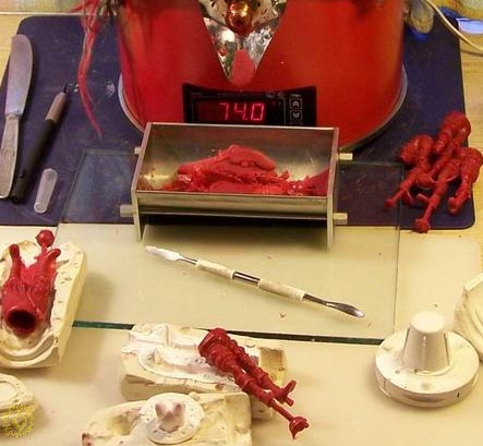
As it is written in correctly assembled system doesn`t need any alignment, it starts to work immediately and will further share you with joy a long winter evenings :)


