Compressor – vacuum pump

So, there was a task to make compressor for providing of compressed air to
above mentioned wax injector. Air consumption for injector is minimal; the main
condition is continuously pressure control. Pressure should be controlled in
scale of 0,5 up to 2 kg/cm2. But anyway the amount of air should be enough to
connect the aerography device, as well as paint sprayer with nozzle up to 0,5 mm
(with receiver, certainly).
But anyway – not to multiply the devices under my table (due to the space
limits of my flat), this device should be strong enough to make vacuum needed
for production of formed amount, as well as for vacuum production of
two-components rubbers. (I`d like to inform that it will not properly operate
with thick solutions like Vixint).
The most available parts for this purpose always were compressors from fridges.
That`s why I asked my familiar worker in fridge repair station to select one
compressor which is maximal strong and most convenient. I obtained the
compressor. Although I don`t know which fridge the compressor belonged to. I was
so excited to receive the compressor that I forgot to ask :o)
So, about compressor. In first I cut the head of compressor, in order to get an
access to inner parts of compressor for further work. Inner parts of compressor – view from the
side of minus line. In upper left side is switch on relais located. You
should fix it in proper position only – vertical, head is up.
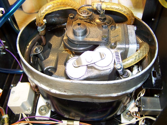
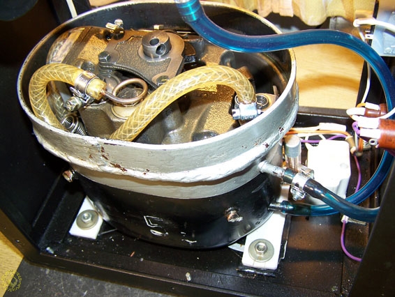
Inner parts of compressor, view from the
side f plus line. For this, I purchased oil-resistant hoses in
auto-parts store.
There is shown on picture why you should not rotate compressor. Motor is
hanged in middle of housing by meaning of three springs. These springs are
fixed to the wedges, inserted in earings of housing. Motor should be removed
by lifting it in direction upstairs. Than you should cut all not useful
parts. Plus and minus lines should be connected by oil-resistant pipes,
connected to rests of cooper pipes inserted in housing. Now you can do it
not where they are available, but where it is convenient for you.
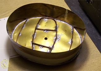
Cover.
The previously cutted piece is not suitable because oil should flow on
cover to inside of tank. I had to do the cover from brass foil, using
soldering. There are reinforcement ribs inside, on outside I glued linoleum
for noise damping. On cover`s top is breather valve located.
As has been found out, if you make proper sealing of minus and plus pipes,
the pressure inside of chamber will not be changed (atmosphere). It means, cover
is necessary for oil collection in order the dust will not get inside. Please
notice – shaft has a hole, there is oil pouring out from all sides.
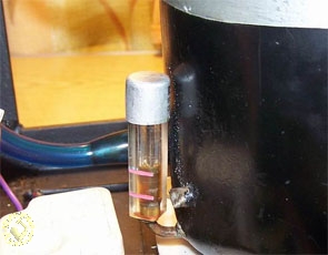
Than, I made removable level measuring device. Compressor (like all oil
compressors) is driving oil fog, that `s why general oil level is continuously
decreasing. Indicator made of plexiglass (made from old handle), with marks
“min” and “max”, will be fixed on thread with sealant.
Indicator is covered by cap against dust, but not airtight.
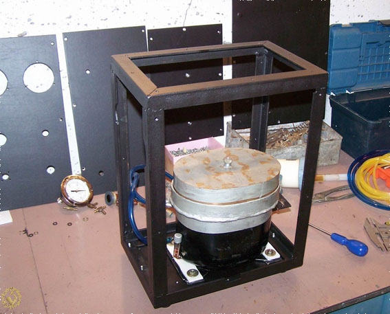
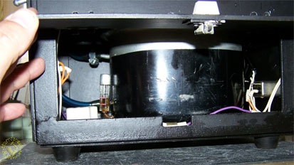
Please put all the parts in housing. Frame should be welded from steel
L-profile with dimensions of 25x25mm. Walls can be made from every material.
I found aluminium 3 mm. In order to check oil level without dismantling of
half of device, I made on the right sidewall door with latch.
Hereby please few words about cable system. As you`ve probably already
recognized, there are two systems in this device: electric and hydraulic
one. Don`t take me a genius, please (:0).
Let`s begin with pneumatic. Electric system is logical continue of
pneumatic.
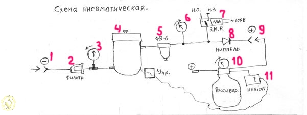
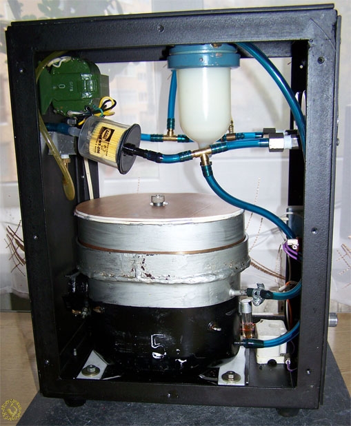
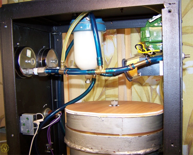
1- Minus input (blowing-in fitting)
2- Incoming filter. Cleaning of incoming air. Car precision filter of type
FT-206.
3- Manometer to check vacuum level. At that time there wer no normal manometers
available, that`s why I took one with scale 0 up to 2 kg/cm2 and aligned arrow
on 1 kg/cm2. It will be an indicator. Anyway there is a normal one on vacuum
chamber, therefore I use it.
4- Compressor, taken from fridge
5- Air filter of type FV-6. Consumption up to 6m3/h, or up to 100l/min. Is in
serial production in Russia. You can buy it by Google. Filter has oil refluxing
plug, it is specially made for collecting it.
6- Normal manometer 0-2 kg/cm2. Acc.to test results, compressor can make
pressure until 6 kg/cm2, but this manometer is enough for my purposes.
7- Electro-pneumatic (discharging ) valve. Please find information about it
below.
8- Back valve. Please find information about it below.
9- Output forcing fitting
10- Receiver. External device for compressor
11- Pneumo-regulating device. It`s fixed on receiver. It`s in use for automatic
pressure control in receiver. This device has screw for control of pressure.
When there is reduction of pressure in receiver, pneumo-regulating device is
responsible for switch on the compressor.
Attention! Compressor should not be switched on in main pipe with pressure.
Otherwise the start winding will burn. After start of compressor`s motor,
increasing of current through working winding occurs. Coil of start relay will
take the core element with contact surface in. Contacts are feeding the start
winding. Motor is starting to spin fast. After motor`s spin up, the current will
decrease through work winding. Under gravitation force, core element falls down
and interrupts the coil winding.
That`s why the devices specified by digits 7 and 8 are needed.
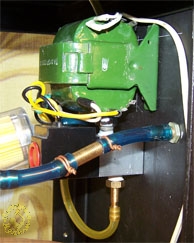
I had no electric pneumatic valve of 220V, that`s why I had to put
transformer. I hope you will not repeat my trial. (Nowadays on web-market there
are devices available which can replace devices specified on my plan by digits 7
and 11. These devices are called pressure relay, or – pressure switcher. There is no pressure
control in these relays, but you can add the reductor on output area).
There is normal-open couple of fittings on valve. After switch on of
compressor, the valve is closed, air is going out through back valve to
receiver. Then you should inflate the receiver. Compressor is going to be
switched off, also the valve, the valve is bleeding (to atmosphere) the air from
area “compressor – back valve”. If there is no back valve, air from receiver
will go out.
But you don`t need it, do you?
Electric
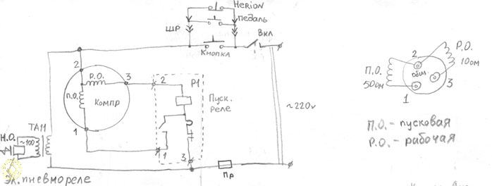
So, here everything should be clear.
PR – it means fuse Power is provided by switcher, but usage of switcher is not
necessary – anyway the power of compressor will be switched on by upper buttons.
So, the most upper – is pneumatic-electric relay on receiver. Then you can see
pedal with button. I use it for creation of vacuum.
Relay or pedal is connected by ØÐ`s sockets.
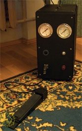
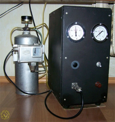
As a receiver I used old fire extinguisher. There is “switch on” button
placed above SHR socket. This is needed to check compressor in operation when
external control is not connected. In first specification, there was an option
to switch on the oil level marking lamp.
Meanwhile, few words about oil. The question is not so easy as it seems to be
from first look. You can use the special compressor one of type VDL100,
certainly, but we don`t prefer the easy way, do we? That`s why I used motor
oils. The motor oil (which is OEM for Russian automotive plant LADA / Zhiguli)
has obtained pure viscosity level, it didn`t reach the requested distance on
hole inside shaft. It happened in non-heated garage condition. The best was
KAMAZ motor oil. I even didn`t tried to test compressor oil.
So, it`s all. The device is under table. There are two pipes going outside
only. If I missed something, then I will add it.


