Homemade muffle electric kiln (small one)

Here I describe the construction of economical electric muffle oven of small
size. Oven`s capacity is 500 Wt, theoretical temperature is up to +800°C, but I
didn`t heat it up till this temperature, because I have more serious oven for
this purpose. Peculiarity of this construction is its simplicity and the most
low cost of materials. Similar construction you can make from available
materials within few days, though the most time will be spent on heating of
oven`s muffle.
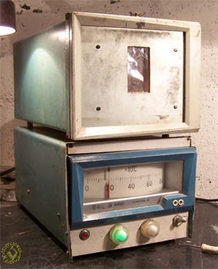
Muffle oven assembled. This oven consists
of two fastened bodies. Muffle element is located in upper body, control
box is located in bottom body.
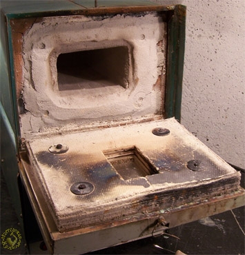
Upper body of oven with open door. In
body`s centre there is the muffle element. Thermo insulation of door, as
shown on picture, is made by meaning of asbestos cardboard, fixed on
studs. Window is covered by two plies of mico with certain gap between
plies.
I recommend you to make oven in different bodies like I did. This approach
allows you not to face problems with cooling of control box of several fans.
Upper body will be warm and will cause the air draw, which (enhanced by
perforation of bottom body) will be enough for cooling of temperature
controller.
Muffle manufacturing
Muffle oven you can make using a lot of approaches. You can take piece of
ceramic pipe. It is better to take mullite-silica of type MKR, or pipe from old
rheostat, or from large fuse.
If you prefer square-shaped chamber, it is adviseable to make laying by
yourself. As I give here advises based on my own experience, hereby please
receipt of my muffle oven.
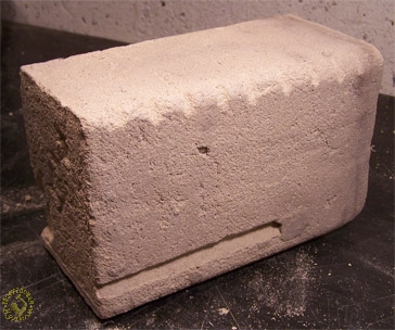
Muffle oven without pipe system. Please
pay attention to grooves on corners of muffle oven. These grooves are a
support, in order to avoid the coil while plastering. There is a groove
for thermocouple placed on upper part. Thermocouple should be close to
coil.
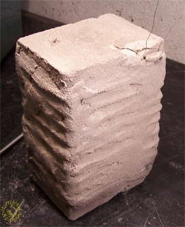
Muffle oven assembled. After placement of
coil, it will be covered by the similar compound like the muffle
consists of. Coils` ends are to be fixed by loop of mico-tape. Don`t
forget to put core bar under coil. When the muffle will be dry, please
take core bar away and there will be hole for thermocouple.
Kaolin (kaolin clay) – 1 part. You can take this material from porcelain
plant. There is a lot of this material there, they produce dishes, bathroom
equipment, electrotechnic ceramic. If you don`t find this material, you can use
any clay of greasy level.
Sand – 3 parts. There is better to use pit-run sand than sand gained from a
river`s bank.
You should properly mix it, put a water until condition when piece of sand is
stable, put it in plastic bag for couple of days. Then we mix it again, till
uniformity is achieved. After that you can make a muffle oven.
Reference.
There is a lot of materials available on market which was in the past not the
case. Now I use the following compound for work of this kind.
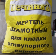
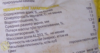
Mortar, manufactured in Pechnik LLC
(Ekaterinburg, Russia), and its characteristics. Please notice it is
ready mortar, it contains filler, in order not to loose the volume while
drying. That`s why you should add sand in lower amount.
So, modeling of muffle. Square-shaped muffle is modeled in square-shaped
wooden case. Muffle brick (with flat bottom and bowed top) has to be made in
the same casing. Dimensions of box for casing are: muffle overall dimensions
plus 3-5% added due to upcoming shrinkage. Muffle brick should be placed
inside of box only, because otherwise cracks are to be expected due to the
shrinkage process. In order to avoid the sticking of the muffle brick to the
box` walls, please cover the walls by plastics. If the compound is more dry,
you can cover wall with paper. Therefore you can spend drying time.
After the muffle brick is formed, it should be dried several days. When
muffle`s walls are hard enough, please turn muffle brick over and put muffle
brick free from box.
Then, if nevertheless brick is not hard enough to be winded by coil, it
should be dried on calorifer or in oven. Then brick should be dried by
temperature up to + 900°C. If there is any problem with burning, in worst
case you can use the dry non-burned muffle. But there will be not enough
hardness.
If muffle is hard enough, it should be winded up with coil, paste should be
put on, and muffle assembled should be dried and burned. It is better to do
it assembled, because paste will keep better on half-dry muffle. Please
notice that there are no caves inside of coil, that everything is filled
with paste. Otherwise there will be local overheating of nichrome.
Calculation of heater
There are a lot of materials about calculation of heater in Internet. All
these materials have their own level of scientific value. For instance, on
web
page you can not only read several conclusions, but you can make your own
calculation on web page integrated calculator. Input data are oven`s capacity,
heater`s material, temperature of heater, temperature of heated part,
construction and positioning of heaters. As output we have diameter and length
of heater`s wire. But if we will have attentive look, we will recognize diameter
is chosen based on material lean principle and conditions of operation are close
to ideal.
Everything is usually quite a contrary in reality. Usually, the man has a piece
of nichrome wire in garage, and he is thinking about – how to use it with more
efficiency. And there are a lot of questions about oven`s capacity.
That`s why I show you here my procedure of calculation. My procedure seems to
be not such scientific-based as others, but it is based on real life.
In first line, you should select the suitable capacity of oven. Capacity has
direct relation to muffle`s dimension and applied fettling. You define size of
muffle, taking into account size of parts to be heated.
As for modern ovens where fibrillar heat-insilators (MKRV, SHPV-350) are used,
approximately capacity related to on 1L of its volume will be:
Oven`s chamber volume (L)
Capacity (Wt/L)
1-5
500-300
5-10
300-120
10-50
120-80
50-100
80-60
100-500
60-50
Supposed, we have chamber`s volume 3L, then capacity of oven will be 1200Wt. I
have oven`s volume a little bit above 1L, hence heater`s capacity will be 500Wt.
Then, let`s calculate current related to heater:
I = P/U= 500/220 = 2,27 A
and resistance of heater:
R = U/I = 220/2,27 = 97 Îì
Then we have a look into our spare parts collection and search nichrome
of available diameter. I had it of 0.65 mm. then acc.to chart we will define if
nichrome will survive requested current.
Diameter (mm)
0,17 0,3 0,45 0,55 0,65
0,75 0,85
Allowed current (À)
1
2 3
4 5
6 7
As we see, having diameter 0,65mm – the allowed current is 5A, so
nichrome will tolerate our given value of 2,27A of power reserve. Generally,
while select of heater, you should take the wire of more thickness
available, because then we have more power of reserve of temperature and
more life time of heater.
The maximum operating temperature of the
heating elements depending on the diameter of the wire

ATTENTION please! It has double effect. We have limits to select the
thickest wire. In order to obtain the calculated value of 97Ohm, you have to
enhance wire`s length which could be impossible due to design principles.
Using chart we define the nominal resistance of 1 m of wire:
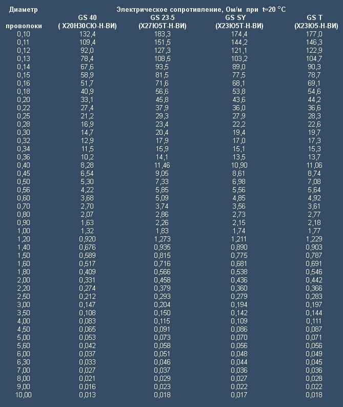
Using chart we define for diameter 0,65mm – the nominal resistance will be
3,2 Ohm/m (it will be further proved by measurement done with device). Hence,
wire`s length will be:
L = R/3,2 = 97/3,2 = 30 Ì
Here we see consequences for diameter “fro reserve” – we have additional wire`s
length. But it is not a problem because I don`t plan to wind this wire up – in
this condition – and there is a certain danger not to get it out of control and
to get coil-winding short circuit on our muffle.
This wire should be winded up in bar. The wire`s end
with bar together will be fixed in drill socket of drill bench, or: in
socket of hand drill. Wire will be feeded under some tension.

While winding up you should meet the following recommendations. If there is
wire of diameter less than 4,5mm – diameter of bar should be not less than:
- for nichrome wire = 4x of wire diameter;
- for fechrale wire = 5x of wire diameter.
For all alloys with diameter more than 4,5mm – diameter of bar should be = 6x
of wire diameter.
There is one peculiarity more while work with fechrale. In comparison to
nichrome, fechrale after burning will be fragile, therefore it is to be handled
with care.
Stretch out the ready coil evenly – until the length suitable for muffle`s
winding is achieved. But no more than this length, because after stretching it
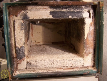
is difficult to be compressed, then. We should wind up the coil on muffle
surface (on grooves) as shown on picture 4, and put the paste.
Then we put our muffle in metal housing.
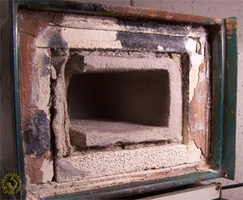
Oven`s fettling. The main fettling is made
by blocks of grog bricks of type SHL-0,4 (low weight, fireproof clay).
Brick is easy to be processed by tooling, as
described above. Please pay
attention to hole in back side of brick intended for thermocouple and
two holes for nichrome wire outcome.
Muffle is placed in fettling. While
placement the sidewall of muffle was damaged, but it is not a problem,
it will be repaired after placement by using the same paste.
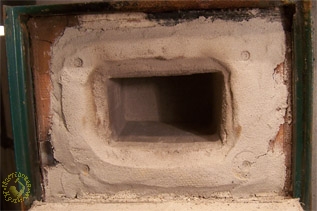
Heat chamber assembled. Wall is finished,
cracks are sticked up with paste. Above muffle`s throat, the paste will
be put, in amount a little bit more than needed. Then please cover it
with plastics and close the cover. There will be cover`s imprint on
paste` surface. Plastic will be removed and all the stuff will be put
for drying. Gaps between cover and chamber should be as minimal as
possible.
I`d like to warn you against some errors you can make while manufacturing
of the fettling.
First of all I`d like to warn you against using of asbestos. Sure, it has
melting temperature by +1500°C, but even by +800°C it looses chemical binded
water and becomes powder. That`s why such parts of asbestos like cardboard
or cord can work until this temperature. Besides, fechrale should not
contact asbestos. I used asbetso because my oven is designed to work with
nichrome and the temperature is below as above mentioned.
As for implementation of liquid glass as a binder. This material is
reasonable to use for muffle making which work below +1088°C, after
exceeding of this temperature the muffle becomes deformed. And, fechral
doesn`t like a contact with liquid glass.
As for fibrous materials (basalt-based) implementation – I have to repeat
what I`ve already mentioned in one of web-forums. It is similar to liquid
glass. It will be produced while blowing from the alloyed composition. It
keeps temperature very well. But these materials have bounding agent which
can not tolerate even +250°C. But the clever retailers on web-markets are
referring to fireproof properties of fiber itself. Nominally – they are
right. But they don`t mention that after the first burning the bounding
agent will burn out and the whole composition will destroy. Although there
are some fibrous cottons on market available which contain fireproof
bounding agent, too, but there is a lack of information. Only indirect signs
– e.g. note that material is intended to be used for bathhouse and
fireplaces. And the retailers are referring to fireproof properties of
fibrous material itself, too. It is not needed that fechral doesn`t like to
be in contact with these materials. It means, if you have some suitable
materials – proven based on your own experience, then please use these
materials only, in order not to make an error. I checked some mullite silica
felts, e.g. of type MKRVH-250 (1300 g). Meanwhile, on the plant in town
Sukhoy Log (Russia), there are ceramic covers in production - Cerablanket,
Cerachem Blanket, Cerachrom Blanket. The first one I checked personally, it
is resistant against direct burner`s flame. The last two must be more fire
resistant. But I didn`t test it by myself.
There are a lot of comments about ovens which are very similar. These
sources evidently are copying materials from each other and are operating
with concept “grog clay”. Normally the common clay has large shrinkage and
is in use as a binding agent. Grog is burned clay. Grog is not sticking, it
is in use as a filler and requires binding agent, e.g. common non-burned
clay. That`s why what does the word combination “grog clay” mean is not
clear.
Control unit
As I promised to provide you the description of the cheapest oven of the
simplest design, the temperature controller will be of corresponding parameters.
There is a good non-expensive one on market available, of type SH-4501, its
price is from 1,000 up to 2,000 RUB. It is the cheapest and simplest one. It has
temperature measuring and control intervals 0(…) +200°C up to 0(…)+1600°C. It
has thermocouple of type XK, XA and PP as measuring element.
Technical description and its
manual of milli-voltmeter of controlling type SH4501. You can
read it when you have free time.
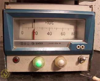
Front panel of control unit. This model is specified for
interval 0 (…)+800°C, with thermocouple XA. View from right to left
side: control unit switch, neon lamp TLO (orange) indicating voltage on
power line, TLZ lamp (green) indicating power switch off and red lamp
indicating break of thermocouple.
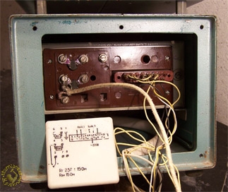
Connection scheme on back side of SH4501. For non-attentive
readers: There is connection scheme shown on plastic cover. Please note:
Compensation wire should go till terminal box with compensating coil.
Such valves for indicator lamps is no longer available, so I recommend to
apply modern type XB2-EV161. They come in red, yellow, green, white and blue
colors.
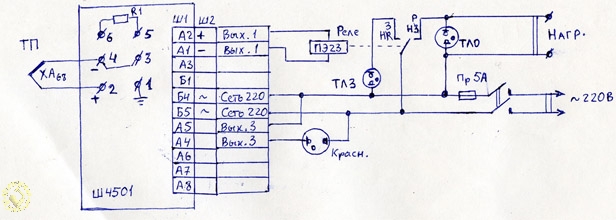
Electric scheme of control unit. If you
don`t find capable switcher of control unit, put it after contacts of
relay PE23. Relay is in set with device SH4501. Capacity of relays`
contacts 500VA in AC circuit. It is not evident on picture: 3 groups of
contacts I made in parallel, that`s why the connected capacity is up to
1500VA. There is corrective on drawing: TLZ lamp is in contact with
normally-closed contacts, TLO – is in contact with normally open
contacts.
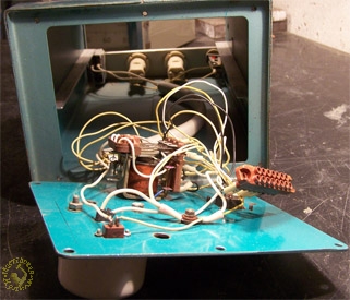
Mounted control unit assembled, in box.
Controller will be put on front, using sliders. Socket will be connected
(on right). Relay has to be fixed on back cover, from inside.
Oven assembled. Back view. As shown,
wires of thermocouple and ends of heater have cooling by ambient air,
without any extra elements. Heater`s wires are to be connected through
terminal box, with ceramic base, if possible. I recommend to use ceramic
inside part of power socket or ceramic cylinder of lamp.
Output lines of thermocouple should be put through terminal box as
well. Piece of compensating wire with appropriate scale system is
connected to the same contacts of terminal box. If you use common wire,
the device will show deformed data, equal to the difference of
temperature between this terminal box and back panel SH4501 with
measuring coil.
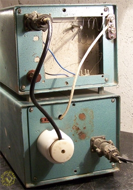
On back panel outside, there is a socket integrated for power connection, and on back side of muffle there is a terminal box mounted for connection of thermocouple. It allows us to use this control unit not with this muffle only, but for temperature regulation of your other devices. You just need to fix thermocouple of this scale system to the terminal box and put plug in power socket.
Few words about home made thermocouple. In order to design the cheapest oven, I used home-made thermocouple with scale system XA. I prefer the home made thermocouples not because of greediness, but because these thermocouples have few inertia compared to those of serial production. But then there is a risk to burn incoming circuits of controller. I wouldn`t like to describe process of thermocouple`s manufacturing in detail because there are good descriptions already available in Internet and special literature (Bastanov, 300 useful advises).

Home-made thermocouple. As material I can use wires from compensating wire with scale system XA. Ends are welded by wolfram electrode in argon medium. If you can`t weld in such way, then you can make it in grafite medium with borax by using powerful transformer. Then please put the thermocouple in ceramic two-channel MKR pipe. It is rather expensive, but you have to buy it.


