Homemade vacuumator (large)

In most cases, if there is needed vacuumizing not of silicons or flood compounds (pitches), but of form-masses for molding acc.to existing models,
vacuum chamber of much more volume is needed, than in vacuumizer as previously described.
I faced such problem, and I had to search of suitable device`s housing. Main requirements to this housing are: inner volume, required for our needs,
and ability to resist pressure from outside. Because in vacuum, pressure on area 10x10cm2 will be 100 kg, and dimensions of chamber are significantly more.
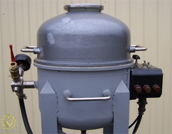
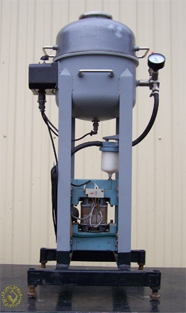
General view from the side of the supposed front panel. Left to the vacuum chamber:
There is a black control unit with integrated lamp. To the right from vacuum chamber: There is a T-joint (or X-joint) fixed.
There are to the T-joint connected items as follows: vavuum manometer, ball valve and hose to air filter.
Hose from air filter is connected direct to vacuum pipe. Length of four racks made of L-shaped steel
is aligned in such way that top section of open chamber is positioned on one`s waistband level.
I found the chamber where vacuumizing of middle sized bucket up to 8L volume of form-mass is possible.
If you can`t find ready housing, you can make it from piece of thick-wall pipe of diameter suitable for your volume of your needs.
Ends of pipe should be covered by steel sheets and welded. Thickness of steel sheet should be more than walls.
Peculiarity of my vacuum chamber is that cover contacts with bottom part of chamber without any hinge joints.
Ends of top and bottom are just evenly proceed on lathe, and top cover will be just lay on base. Sealing is made due to common rubber sealant.
Then the vacuum itself will press the cover. Having radius of chamber 30cm, maximal press force will be 700kg.
Air filter is compulsory to avoid getting of steam and splashes from vacuum
chamber into vacuum pump. As a air filter I used FV-25. But you can use anything
more comprehensive. Main conditions is, that filter has plug on the bottom in
order to evacuate condensed water.
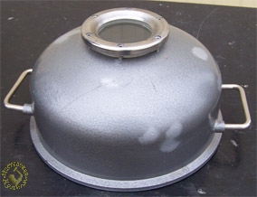
Cover of vacuum chamber. There is a window made, covered by glass of 10mm thickness.
Application of glass is needed, because the form-mass will get more volume under vacuumizing, and main condition is – not to spend moment of ball valve opening in atmosphere.
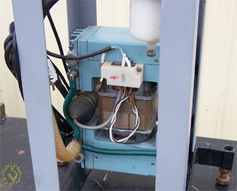
Nowadays it is oil-less pump from pump package-maker. But I plan to replace it by BECOOL BC-VP-114 of oil type, due to its unacceptable noise emission.
Now it`s correct time to have a look inside vacuum chamber and specify main difference to above mentioned
vacuumizer. Vibrations are happening in vertical plane there, because it had small weight of semifinished part and electromagnet vibrator carried its function out very well.
In this case, due to weight increase there is a danger that vibrated plate will be pressed to magnet.
That`s why in this model, weight of form-mass will get in contact to special plate which is designed to
receive the load, and will slide down to the horizontal plane. Vibrations will occur due to unbalanced fan fixed to the plate.
Construction of fan. There is a steel support ring welded to the bottom of vacuum chamber (inside).
Height and diameter of the ring is aligned taking into account dimensions of fan and vibrations amplitude of the plate.
Plate itself is shown as turned over, with fan fixed on it. Plastic pipe (cutted along) is seated on ring.
Surface of this ring is covered by grease, therefore the plate is free sliding on greased plastic.
There is even trace of the ring clear shown on plate. Diameter of plate is certainly lower than inner diameter of chamber, difference is equal to value of amplitude.
By me it is 3-4mm, taking into account the dempers - cutted ends of pipe - on the plate`s edge.
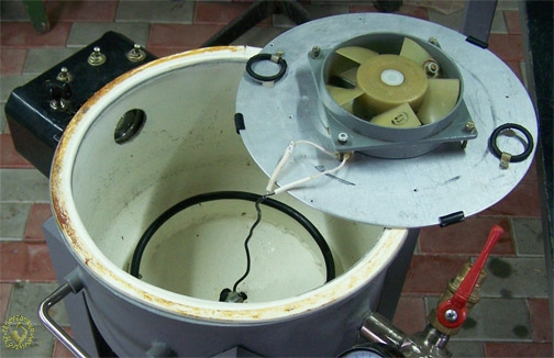
The attentive reader of this work will say: Well, it`s good but plate will rotate and will wind up the cable to the fan. And he will be right. To avoid this, flexible support is made, represented by two rubber rings, fixed on plate, and two hooks, fixed on support ring. Support ring with plastic pipe and two L-shaped hooks. There is a SHR-socket shown in the middle of the chamber`s bottom, with cable leading to fan. You can seal this place with epoxide compound or, by using of glue gun. Plate is turning over and is coming down on support ring, then it is turning clock counterwise. Rubber rings are coming in contact with hooks, and – that`s it. This process will go easier due to holes on plate well visible on picture 10.
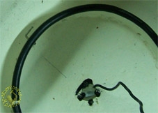
Vibration power is controlling due to selection of weight of screws and washers which are fixed on fan`s propeller (pict.5), as well as by meaning of controller in control unit.
Control unit
I made electric scheme of control unit as easy as possible, because the real reliability begins at the point where there is nothing to be broken. And if something will break, this can be purchased at the nearest store.
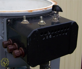
Control unit. On cover, from left to right: light switcher, vacuum pump switcher, vibrator switcher, vibrator controller. There are fuses on left side: lighting, vacuumizer, vibrator.
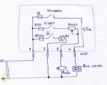
Electric plan of vacuumizer. For vibration control I used wire-based resistor PPB-15D for 1,5 com. I used halogen lamp for 200V, of size MR11, 20 Wt, lamp base G5.3. Application of lamp for 220V allowed me to go ahead without transformer.
And I purchased at the store the ceramic base with thermo-resistance cables.
Please don`t forget to make many holes on top and bottom for cooling the lamp. And please leave a gap between lamp and lens. The lamp`s holder I made in shape as a cooling device.
View on internal mounting of control unit. There is a fastening device of halogen lamp of type MR11 shown. Lamp socket is ceramic with thermo-resistant wires.
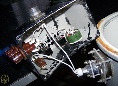
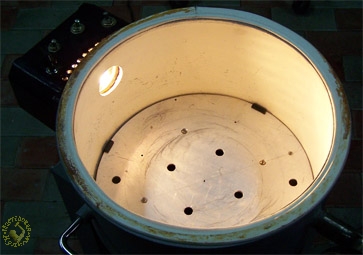
Vacuum chamber lightening. Due to application of thick lens instead of common glass, the light has a good distribution of whole chamber.
There is needed to seal the glass on chamber`s cover and lens of lamp by using of silicon-organic compounds like Vixint.
The silicon sealant will be acceptable at least, too. Main condition is: There should be an even surface.
For those who didn`t worked with vaccumizer – hereby please short explanations. You shouldn`t flood the form-mass in tank till it is absolutely fully.
While vacuumizing process, the form mass will boil and enhance its volume. Since form-mass reaches edges of tank – you should discharge overpressure by opening ball valve.
Please proceed it several times, till free air will not go out. Main condition is – not to mix this ask with common tire`s boiling which occurs in vacuum by pressure of -0,9 kg/cm2.
Vaccumizer (vacuum chamber) in use. First, I switched lightening on, then I started the vibrator`s motor. I enhanced the amplitude and frequency of vibration. Then I switched vibrator and pump off. I slacked the vacuum away and opened the cover.


